Voltage Multiplier Circuit
A Voltage Multiplier Circuit, is a special type of rectifier circuit which produces a DC output voltage which is many times greater than its AC input voltage. Although it is usual to use a transformer to increase the voltage, sometimes a suitable step-up transformer or a specially insulated transformer required for high voltage applications may not be available. One alternative approach is to use a voltage multiplier circuit.
Voltage multipliers are AC-to-DC voltage converters used in electrical and electronic circuit applications such as in microwave ovens, cathode-ray tube (CRT) field coils, electrostatic and high voltage test equipment, etc, where it is necessary to have a very high DC voltage generated from a relatively low AC voltage. The high voltage produced by a voltage multiplier circuit is in theory unlimited, but due to their relatively poor voltage regulation and low current capability most multiplier circuits produce voltages in the range of about 10kV to 30kV with a low current of less than ten milliamperes.
Voltage multiplier circuits are constructed from series combinations of rectifier diodes and capacitors that give a DC output equal to some multiple of the peak voltage value of the AC input voltage. By adding a second diode and capacitor to the output of the simple half-wave rectifier, we can increase its output voltage. The most commonly used type of voltage multiplier circuit is the Half Wave Series Multiplier also known as a “cascade voltage doubler”.
Voltage Doubler
The Voltage Doubler circuit shown consists of only two diodes, two capacitors and an oscillating input voltage. This simple diode-capacitor pump circuit gives a DC output voltage equal to the peak-to-peak value of the input. In other words, double the peak voltage value because the diodes and the capacitors function together to effectively double the voltage.
During the negative half of the sinusoidal input waveform, diode D1 is forward biased and conducts charging up the pump capacitor, C1 to the peak value of the input voltage, (Vp). Capacitor C1 now acts as a battery in series with the supply. At the same time diode D2conducts via D1 charging up capacitor, C2. During the positive half cycle, diode D2 is forward biased and diode D1 is reverse biased, adding the peak AC input voltage to the voltage Vpacross capacitor C1 and transferring this summed voltage to capacitor, C2 through diode D2as shown.
DC Voltage Doubler Circuit

The voltage across capacitor, C2 is equal to the sum of the peak supply voltage and the voltage across input capacitor, C1. Then a half wave voltage doubler’s output voltage can be calculated as: Vout = 2Vp, where Vp is the peak value of the input voltage.
The advantage of “Voltage Multiplier Circuits” is that it allows higher voltages to be created from a low voltage power source without a need for an expensive high voltage transformer as the voltage doubler circuit makes it possible to use a transformer with a lower step up ratio than would be need if an ordinary full wave supply were used. However, while voltage multipliers can boost the voltage, they can only supply low currents to a high-resistance (+100kΩ) load because the generated output voltage quickly drops-off as load current increases.
By connecting the output of one multiplying circuit onto the input of the next (cascading), we can continue to increase the DC output voltage to produce voltage triplers, or voltage quadruplers circuits, etc, as shown.
DC Voltage Tripler Circuit
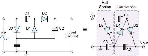
A “voltage tripler circuit” consists of one and a half voltage doubler stages. This voltage multiplier circuit gives a DC output equal to three times the peak voltage value (3Vp) of the sinusoidal input signal. Note: the real output voltage will be 3(Vp – Von).
DC Voltage Quadrupler Circuit

If a voltage tripler circuit can be made by cascading together one and a half voltage multipliers, then a “voltage quadrupler circuit” can be constructed by cascading together two full voltage doubler circuits as shown. The first stage doubles the peak input voltage and the second stage doubles it again, giving a DC output equal to four times the peak voltage value (4Vp) of the sinusoidal input signal. Also, use large value capacitors to reduce the ripple voltage.
By cascading together individual half and full multiplier stages in series, any desired amount of voltage multiplication can be obtained and a cascade of “N” doublers, would produce an output voltage of 2N.Vp volts. For example, a 10-stage voltage multiplier circuit with a peak input voltage of 100 volts would give a DC output voltage of about 1,000 volts or 1kV, assuming no losses. However, the diodes and capacitors used in all multiplication circuits need to have a minimum reverse breakdown voltage rating of at least twice the peak voltage across them. One word of caution!. Multi-stage voltage multiplication circuits can produce very high voltages, so take care.
The Voltage Multiplication Circuits shown above, are all designed to give a positive DC output voltage. But they can also be designed to give negative voltage outputs by simply reversing the polarities of all the multiplier diodes and capacitors to produce a negative voltage doubler.