brock

Thursday, July 26, 2012

Graphical LCD interfacing with pic controller

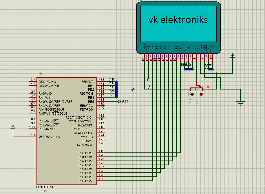
Here is a sample code to Interface Graphical LCD to a PIC Controller


CODE

#define                KS0108
#include "LibraryHardware.h"
#include "LibraryChar.h"
#include "LibraryUniversalDisplay.h"
#include "LibraryData.h"

void pic_init(void);

void main()
{
int i,j;
pic_init();                                                                             //initialize PIC
glcd_init();                                                                          //initialize GLCD
for(;;){
                for(i=0;i<8;i++){
                                CHIP_LEFT();
                                glcd_goto(i,0,0);
                                for(j=0;j<=63;j++) glcd_write(img1[128*i+j]);
                                CHIP_RIGHT();
                                glcd_goto(i,0,0);
                                for(j=0;j<=63;j++) glcd_write(img1[128*i+j+64]);
                }
                delay(1000);

                for(i=0;i<8;i++){
                                CHIP_LEFT();
                                glcd_goto(i,0,0);
                                for(j=0;j<=63;j++) glcd_write(img2[128*i+j]);
                                CHIP_RIGHT();
                                glcd_goto(i,0,0);
                                for(j=0;j<=63;j++) glcd_write(img2[128*i+j+64]);
                }
                delay(1000);
}             
}

void pic_init(void)
{
TRISA=0b00101111;
TRISB=0b00000000;
TRISC=0b00000000;
TRISD=0b00000000;
TRISE=0b00000111;
set_digital();
PORTA=0b00010000;
PORTB=0b00000000;
PORTC=0b00000000;
PORTD=0b00000000;
PORTE=0b00000000;
}

Tuesday, July 24, 2012

Touch Switch

This circuit demonstrates the principle and operation of application based on touch sensor. The circuit is divided into three parts: Input, 555 timer and output. A touch plate is used for the input and output can be seen across an LED or a buzzer. Some application of the circuit include touch based blinking lights, touch buzzer, touch switch etc.


The touch plates is connected to the trigger pin of the 555 timer IC. When we touch the touch plates the output of the touch plates becomes zero thereby providing an active low trigger to the IC 555. The IC is configured in the monostable mode .The output of the IC is a pulse whose frequency is set by theresistor (R1) and  capacitor (C1) according to the formula [F=1/(1.1*R*C)]. In this case it produces a pulse with frequency of about 0.9 hertz and time period of 1.1 seconds. In monostable mode pin7 (discharge pin) and pin6 (threshold pin) are shorted while R1 is connected between pin7 and Vcc and C1 is connected between pin 6 and ground. Reset pin (pin4) is connected to Vcc while control pin is connected to ground through a capacitor. The output can be observed on the LED, which glows for a small duration. This circuit can be used in the following applications:
To detect stray voltages produced by mains or to detect electrostatics build up in a room.
To make touch buzzers.
To implement touch switches like for a bell.
circuit 2, shows an improved version of this circuit. This circuit has a higher sensitivity as compared to circuit in figure 1. The output of the touch plate is connected to the base of npn transistor T1 (BC 547). The collector is connected to the Vcc through a resistor R1. The trigger pin of the IC is connected to the collector of the transistor. When no input is there on the base of the T1, T1 is in cut off state and hence the trigger pin is at logic high and therefore 555 do not produce any output. When we touch the plates T1 behaves like a closed switch trigger pin gets connected to ground, thereby producing the output at pin 3 of the IC.

Automatic Night Lamp


Ever imagined how the street lights would turn on automatically in the evening and go off in the morning? Is there anyone who comes early morning to turn off these lights? The following circuit can perform this job properly. This circuit uses the output from a simple light/dark activated circuit and drives a relay in its output which can be further coupled to switch on/off an electrical appliance in a household.
An appliance can be made dark or light activated by slightly changing the circuit’s configuration.  This idea finds numerous applications such as, automatic watering of gardens at evening, automatic night lamp, dark activated siren and so on.

 A light dependent resistor (LDR) is used in this circuit to provide input to a comparator of LM339 (refer Automatic lightdark indicator). The output pin of the comparator goes high depending on the configuration of LDR so that it can be made light or dark activated. This output is connected to a transistor T1 (BC 547) which acts as a switch for the relay.
The high output of the comparator provides the necessary forward bias to the base-emitter junction of the transistor T1. Thus T1 jumps from cut off to saturation state and collector current flows. This collector current energizes the relay coil. The magnetic field produced by the relay coil shifts its connection from NO state to NC. An appliance connected to NC contact gets switched on.
When the output of the comparator is low, it is insufficient to drive the transistor T1 to saturation. Hence T1 moves to cut off and the collector current ceases to flow. Thus the relay coil gets de-energized and it switches the state from NC to NO mode. It is important to note that resistor R2 (20k) is provided at the base of T1 to check the base current.