brock

Thursday, July 26, 2012

DC Motor Interface with 8051 Microcontroller


A DC motor runs with the help of Direct Current. It produces torque by using both electricity and magnetic fields. The common term used to refer both fields is Electromagnetism. When a current carrying conductor is placedin the external magnetic field, then it will experience a force proportional to the current in the conductor and strength of the external magnetic field.
                        F = B*L*I
Where F is force in dynes.
            B is flux density in lines per square centimetres.
            L is length of the conductor
            I  is current in the conductor.

The same principle is used in the DC motor. The DC motor has rotor, stator, field magnet, brushes, shaft, commutator. The DC motor requires more current to produce initial torque than in running state.

Schematic

Code

#include
# define MOTOR P0

void delay(unsigned int);

void main()
{
    while(1)
    {
     MOTOR=0X01;
     delay(20);
     MOTOR=0X02;
     delay(20);
     MOTOR2=0X0A;
     delay(20);
     MOTOR2=0X08;
     delay(20);
    }


with this code u can control two motors in clockwise as well as counter clockwise...

Graphical LCD interfacing with pic controller

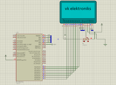
Here is a sample code to Interface Graphical LCD to a PIC Controller


CODE

#define                KS0108
#include "LibraryHardware.h"
#include "LibraryChar.h"
#include "LibraryUniversalDisplay.h"
#include "LibraryData.h"

void pic_init(void);

void main()
{
int i,j;
pic_init();                                                                             //initialize PIC
glcd_init();                                                                          //initialize GLCD
for(;;){
                for(i=0;i<8;i++){
                                CHIP_LEFT();
                                glcd_goto(i,0,0);
                                for(j=0;j<=63;j++) glcd_write(img1[128*i+j]);
                                CHIP_RIGHT();
                                glcd_goto(i,0,0);
                                for(j=0;j<=63;j++) glcd_write(img1[128*i+j+64]);
                }
                delay(1000);

                for(i=0;i<8;i++){
                                CHIP_LEFT();
                                glcd_goto(i,0,0);
                                for(j=0;j<=63;j++) glcd_write(img2[128*i+j]);
                                CHIP_RIGHT();
                                glcd_goto(i,0,0);
                                for(j=0;j<=63;j++) glcd_write(img2[128*i+j+64]);
                }
                delay(1000);
}             
}

void pic_init(void)
{
TRISA=0b00101111;
TRISB=0b00000000;
TRISC=0b00000000;
TRISD=0b00000000;
TRISE=0b00000111;
set_digital();
PORTA=0b00010000;
PORTB=0b00000000;
PORTC=0b00000000;
PORTD=0b00000000;
PORTE=0b00000000;
}

Tuesday, July 24, 2012

Touch Switch

This circuit demonstrates the principle and operation of application based on touch sensor. The circuit is divided into three parts: Input, 555 timer and output. A touch plate is used for the input and output can be seen across an LED or a buzzer. Some application of the circuit include touch based blinking lights, touch buzzer, touch switch etc.


The touch plates is connected to the trigger pin of the 555 timer IC. When we touch the touch plates the output of the touch plates becomes zero thereby providing an active low trigger to the IC 555. The IC is configured in the monostable mode .The output of the IC is a pulse whose frequency is set by theresistor (R1) and  capacitor (C1) according to the formula [F=1/(1.1*R*C)]. In this case it produces a pulse with frequency of about 0.9 hertz and time period of 1.1 seconds. In monostable mode pin7 (discharge pin) and pin6 (threshold pin) are shorted while R1 is connected between pin7 and Vcc and C1 is connected between pin 6 and ground. Reset pin (pin4) is connected to Vcc while control pin is connected to ground through a capacitor. The output can be observed on the LED, which glows for a small duration. This circuit can be used in the following applications:
To detect stray voltages produced by mains or to detect electrostatics build up in a room.
To make touch buzzers.
To implement touch switches like for a bell.
circuit 2, shows an improved version of this circuit. This circuit has a higher sensitivity as compared to circuit in figure 1. The output of the touch plate is connected to the base of npn transistor T1 (BC 547). The collector is connected to the Vcc through a resistor R1. The trigger pin of the IC is connected to the collector of the transistor. When no input is there on the base of the T1, T1 is in cut off state and hence the trigger pin is at logic high and therefore 555 do not produce any output. When we touch the plates T1 behaves like a closed switch trigger pin gets connected to ground, thereby producing the output at pin 3 of the IC.